Starting a Stress/Strain Analysis
5. Select MinimalFEM Analysis
The first step is to indicate to modelbuilder that we are going to specify a MinimalFEM simulation. In the sidebar’s Attribute Editor tab, there is one sub-tab labeled Analysis containing two selection fields labeled Simulation and Mesher. In the Simulation field, select MinimalFEM which, at the present time, is the only choice available. In response, ModelBuilder-2D will display a second tab labeled MinimalFEM and that tab will also display a red alert icon indicating that one or more fields in that tab are currently invalid.

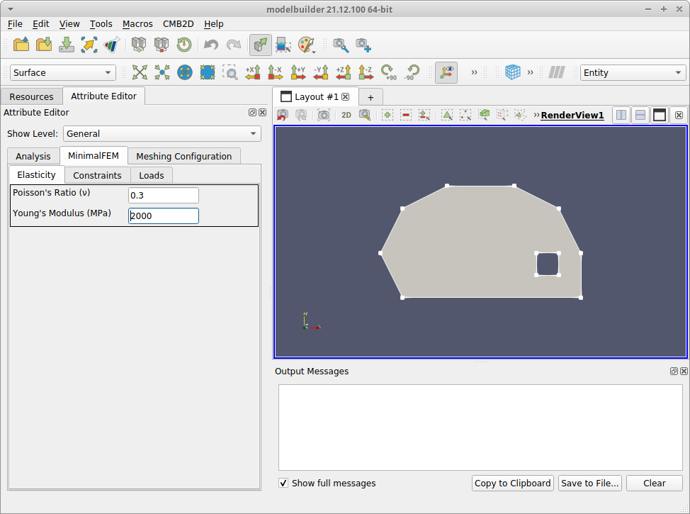
6. Set Elasticity Properties
We can now specify the material properties to pass to the solver (which are used to construct the stiffness matrix for the analysis). Because our solver is limited to isotropic, homogenous media, elasticity can be specified with two scalar values from Hooke’s law: Young’s modulus and Poisson’s ratio. Clicking on the Minimal FEM tab, you can see that it contains three children tabs labeled Elasticity, Constraints, and Loads. In the Elasticity tab, there are two fields for Poisson’s Ratio and Young’s Modulus. The Poisson’s Ratio field is already set to a value of 0.25, which is a default value set in the MinimalFEM.sbt file mentioned above. The yellow background indicates that the current value is the default. Change that value to 0.3 to represent a typical steel. The background changes to white to indicate you are not using the default value.
The Young’s Modulus field has no default value, and the red background indicates that the value is invalid (in this case, missing). Enter a value of 2000, which is typical for steel, and note that the background color changes to white. Also notice that the alert icons in the Elasticity and MinimalFEM tabs also disappear when the value is entered.
7. Save the Project
With the model imported and the analysis specified, it is a good time to write the project changes to your file system. To do that, go to the CMB2D menu and select the Save Project item. When you do that, ModelBuilder-2D writes two files to a resources subdirectory under the project directory. One file, with name starting CMB2D-ANALYSIS- and an extension of .smtk is the attribute resource, which stores the data entered in the “Attribute Editor”. The other file, with name starting CMB2D-MODEL- and extension .smtk is the model resource, which stores the geometric model (including topology) that was imported from the ppg file. Resource files can be individually loaded into modelbuilder, however, we recommend using the CMB2D project menu to open and close all resources atomically.
With the elasticity properties set, we will proceed to assign boundary conditions in the next section.